Antireflective textured coatings
Elimination of undesired reflection from optical surfaces is important for many technologies. In photovoltaics reduction of reflection from solar cells leads to enhancement of their efficiency. In telescopes and similar optical devices elimination of reflection is required to achieve better quality of image. Antireflective coatings allow to reduce the glint from a covert viewer's binoculars or telescopic sight.
To reduce reflection one can use single-layer quarter-wave coatings. Their work is based on destructive interference in the beams reflected from the interfaces, and constructive interference in the transmitted beams. However, as a result, single-layer coatings possess antireflective properties only for limited range of wavelengths and incidence angles.
To extend this range multi-layer coatings can be used. They are based on the same principle as single-layer coatings: destructive interference between beams reflected from different layers. Layers thicknesses and refractive indices should be chosen to achieve minimal reflectance in a wide wavelengths or incident angles range. The disadvantage of multi-layer coatings is difficulty to find materials with required refractive indices.
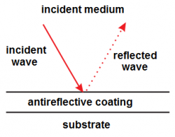
Alternative to multi-layer coatings are layers with continuously changing refractive index. Their application allows to achieve small reflectance in a wide spectral range. However, their manufacturing encounters problems with thermal mismatch, adhesion and stability of thin-film stack.
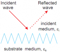
An alternative method for the reflection reduction consists in texturing the surface with 3D pyramids or 2D grooves (gratings). This method was discovered in nature by studying structure of moths' eyes. Surfaces of moths' eyes are covered with a natural nanostructured film. The film structure consists of a hexagonal pattern of bumps, each roughly 200 nm high and spaced on 300 nm centers. Since bumps are smaller than the wavelength of visible light, the light sees the surface as having a continuous refractive index gradient between the air and the medium. It leads to reflection reduction by effectively removing the air-lens interface. This allows the moth to see well in the dark, without reflections to give its location away to predators.
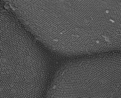
Moth eye.
Textured coatings have antireflective properties for wavelengths much smaller than texture size as well. In this case reflection reduction can be illustrated geometrically: rays should be reflected many times until being reverted back. At the same time transmitted rays deviate from the incident direction that leads to light trapping effect used in solar cells.
Since the seventies of the last century there is a lot of experimental studies of the properties of textured surfaces. Many reports on successful fabrication of the antireflective nanostructured surfaces appeared recently. Their use in the solar cell technology may lead to one or two orders of magnitude reduction of the surface reflection.
In the following we discuss antireflective properties of textured coatings at the whole range of their sizes including long and short wavelength limits.
Long wavelength limit
If wavelength is much larger then texture size, optical properties of the textured coating can be described by effective medium approximation. According to this approximation, electromagnetic wave propagates in textured coating as in anisotropic medium with some effective dielectric permittivity. Below we describe how to calculate effective permittivity for following structures:
- structures which are infinite in -direction (dielectric permittivity
depends on
and
only).
- structures which are finite -direction.
- multi-layered structures and structures with gradually changing profile (textured coatings).

In the first case, dielectric permittivity of the structure is periodic in
-plane and does not depend on
.
One can choose
and
axis in such way that effective permittivity will be described by tensor
with 3 nonzero diagonal elements
,
and
.
If structure possesses central symmetry in
-plane, 2 components of this tensor should be equal
.
As an example, let us consider sequence of parallel plates ( changes in one direction only).
is width of each plate,
is distance between them,
is plates dielectric permittivity,
is dielectric permittivity of the environment.
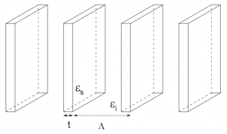
Sequence of parallel plates.
If distance between plates is small compare to wavelength
, electric field can be assumed to be a constant within a plate and between two closest plates.
At the plate interface, normal component of vector
and tangential component of vector
should be continuous.
It leads to the following expressions for components of the tensor
, corresponding to directions which are perpendicular and parallel to plates:
where and
are volume fractions for plates and for environment.
Now lets consider square parallelepipeds which are infinite in -direction. Parallelepipeds are packed in square lattice.
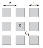
Square parallelepipeds which inifinite in z-direction. Parallelepipeds are packed in square lattice.
Brauer and Bryngdahl proposed the following empirical expression for effective permittivity in and
directions:
where is refractive index averaged value, and
and
are square roots from the following expressions
where ,
and
should be calculated using expressions for plates which are given above.
For infinite cylinders effective permittivity can be calculated using Maxwell-Garnett expression:
where is cylinders filling fraction.
In last two cases effective permittivity is tensor with equal diagonal components
and
due to the central symmetry in
-plane.
Component
is dielectric permittivity average value (it follows from continuity of electric field tangential component, as in derivation for
in the case of parallel plates).
Before we were assuming that structure is infinite along -direction.
However, if the thickness of the structure in
-direction is larger than critical value
, effective permittivity can be calculated as in “infinite” case.
In multi-layered structure each layer is characterized by its own effective permittivity. One can use effective medium approximation for structures with gradually changing profile (like textures coatings) as well. Optical properties of this structure should be similar to properties of the film with gradually changing dielectric permittivity. There are two methods to calculate reflectance from such type of film.
In one method, film is approximated by a multi-layered structure with great number of very thin layers. Dielectric permittivity of each layer is assumed to be constant. Each layer is characterized by transfer matrix and product of such matrices is transfer matrix for the whole structure. This resulted transfer matrix can be used to calculate reflectance. Description of transfer matrix method can be found here1).
Another method to find reflectance, which consists in solving of Maxwell equations in inhomogeneous medium, can be found here 2).
Geometric optics approximation
If wavelength is much smaller then texture size, geometric optics approximation can be used. In this case on can apply ray tracing technique to calculate reflectance. Modeled rays propagate in straight lines inside the texture and get reflected or refracted from the texture interface according to Fresnel equations.
Geometry optimization
In the following we consider surfaces coated by a periodic pyramid-type texture with height .
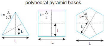
Pyramids bases have the shape of triangles, squares, hexagons and circles (in the last case pyramid is in fact a cone) with the distance between the base side and its center .
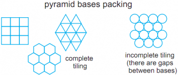
The pyramids are closely packed on the substrate in the triangular or square lattice with the period
.
We will specially distinguish two cases: complete tiling case when pyramids bases touch each other along their whole perimeter (this corresponds to the polygon base pyramids in our study) and incomplete tiling case when there are gaps between bases (this corresponds to cones).
Textured surface is made from glass (the refractive index ).
We consider normal light incidence case.
Effective medium approximation
As we showed before, in the long wavelength limit electromagnetic waves propagate in textured surface as in film with gradually changing effective dielectric permittivity .
Here
direction is aligned along the pyramid axis, with
at the pyramids tops and
at the pyramids bases.
Increase of the pyramids height and decrease of the optical contrast between the incident medium and the texture reduces the reflection.
In the case of complete tiling, the filling fraction at the top of the pyramids is and at the base of the pyramids is
, therefore
and
.
Here
is the pyramids permittivity,
is the incident medium permittivity, and
is the filling fraction occupied by pyramids at
, that is equal to the ratio between cross sectional area of the pyramid and area of the unit cell of the lattice.
Some special profiles can be chosen to reduce the reflection with the increasing
.
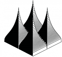
For example, if is polynom of degree
with zero derivatives
, then
.
In particular, for profiles
and
(we assume that
) we have
and
correspondingly.
Let us find a profile characterized by zero derivatives of all orders at the points and
:
,
.
Without any restriction assume that
.
Consider first the infinitely differentiable function
, that is zero with all its derivatives at
and
.
After its integration we get a monotone function increasing from 0 to 1
, where value of
is chosen to ensure
.
Using this 'integral' profile leads to the exponential decrease of the reflectance with the growth of
due to
.
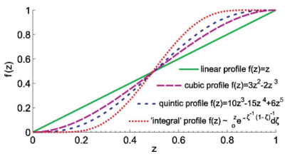
We calculated dependence of the reflectance on for closely packed square pyramids with following profiles:
- ,
. We calculated flat-sided pyramids where width depends linearly on the height. Since filling fraction is proportional to the width squared, we used
, but not
;
- ,
;
- ,
.
For these pyramids we obtained ,
and
correspondingly.
Note that results obtained by effective medium approximation and FDTD are in good agreement. We used Brauer-Bryngdahl expression for the effective dielectric permittivity of square pyramids.
We calculated the reflectance for gradient index film corresponding to a single-periodic grating with the 'integral' profile.
Using this profile leads to the exponential decrease of the reflection with the growth of .
At the incomplete tiling case there are gaps between pyramid bases: .
It causes a discontinuity of the permittivity
at the pyramid bases
:
.
Due to this fact, by increasing
the reflectance tends to a constant value equal to the reflectance between the media with
and
.
To demonstrate this we calculated the reflectance for gradient index film corresponding to cones closely packed in the triangular lattice.
We used Maxwell-Garnett expression for the effective dielectric permittivity of cones.
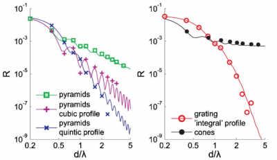
Reflectance for different pyramids. Comparison between results obtained using effective medium approximation (lines) and FDTD (dots).
Geometric optics approximation
In the short wavelength limit the optical properties of textured surfaces do not depend on the wavelength
and are defined by geometry only.
We calculated the reflection for closely packed triangular, hexagonal and square pyramids (complete tiling) and cones (incomplete tiling) for different values of .
Results obtained by using ray tracing technique and FDTD are in good agreement.
The difference between them appearing by increasing
may be explained by the fact that the value of
used in the FDTD model becomes insufficiently large for light diffraction effects to be neglected.
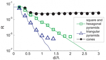
Reflectance for different pyramids. Comparison between results obtained using ray tracing technique (lines) and FDTD (dots).
We obtained exponential decrease of the reflection with the growth for the complete tiling case.
For the incomplete tiling case the reflection tends to a constant value passing a local minimum while
increases.
Below we give our explanation of these results.
We introduce the following ray classification:
- Incident rays.
- Reflected rays formed by incident rays after their reflection from the texture. These rays revert back into the incident medium after some number
of consecutive reflections. Angle of reflectance, amplitude and phase of such rays at each reflection can be calculated using Fresnel equations.
- Refracted rays formed by incident or reflected rays after they get into the texture.
- Secondary rays formed by refracted rays if they leave the texture.
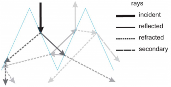
Rays classification.
Only reflected and secondary rays make contribution to the total reflection .
It can be shown that (a) number of reflections inside the structure, necessary for the propagating rays to obtain the backward direction, grows linearly with the texture height. Since after each reflection ray amplitude is multiplied on reflection coefficient form pyramid surface, decreases exponentially with
.
According to our calculations secondary rays make small contribution to the reflection which can be explained by the following considerations.
(b) pyramids deflect secondary rays downward since
, preventing them to revert back to the incident medium.
As a result refracted rays can c) transmit to the substrate directly, d) or move onto the inner pyramid side under the total internal reflection angle.
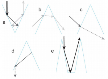
In the case of incomplete tiling (cones) the reflectance tends to the constant value with the growth of passing over a local minimum.
It can be explained by the following considerations.
While
, e) normal rays remain almost parallel to the scatterer surface after the first reflection and some of them go to the gap between the bases not reaching the neighbouring scatterer.
Afterwards they are directly reflected back into the incident medium.
For the cones case almost all incident rays behave in this way, therefore while
the reflectance tends to the substrate reflectance value.
All texture size to wavelength ratios
Here we consider results for all texture size to wavelength ratios obtained using FDTD method.
Consider first the complete tiling case using the results for square pyramids.
Let us fix some value and follow the reflectance
behavior while
increases (see corresponding black curves at the picture).
By the increase of
from
to
the reflectance decreases achieving local minimum at
.
It can be explained by the fact that the effective dielectric permittivity does not depend on the
at zeroth approximation and the reflectance of corresponding gradient index film decreases while
increases.
At
the reflection decreases further passing local minima corresponding to the values of
at which next diffraction orders appear.
However these reflectance oscillations become smaller at greater
while the curve approaches the geometric optics limit.
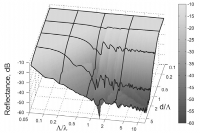
The reflectance from closely packed pyramids with square bases (FDTD results).
In the case of incomplete tiling the minimal reflectance is achieved at of the order of the wavelength.
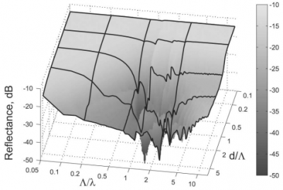
Reflectance from cones closely packed in the triangular lattice (FDTD results).
We come to a conclusion that the optimal texture size is determined by the character of the pyramids tiling. At the complete tiling case the reflection tends to zero at for a fixed ratio
. This is in agreement with the fact that the rate of the reflection reduction with increasing
and fixed
and
is exponential in the geometrical optics limit, and is thus higher than the polynomial rate in the effective medium limit. At the same time small reflectance can be achieved at
of the order of the wavelength. In the incomplete tiling case the optimal value
is of the wavelength order. This is also in agreement with the limiting approximations considered above.
Note that high precision fabrication of completely tiled mactotextured surfaces is a complicated technological task. Fabrication of textured surfaces with periodicity of the order of some hundred nanometers by lithographic technique or etching seems to be more advantageous. A possibility of achieving very small reflection values for texture sizes of the wavelength order is the evidence of this texture efficiency for the visible range.
Textured silicon coatings for solar cells
Using antireflective coatings is one of the way to increase efficiency of solar cells. For this purpose multi-layered coatings or coatings with porous silicon can be used. Coatings with porous silicon act like a film with gradually changing refractive index if porosity is increasing with the depth. However, as we discussed above, these types of coatings are not so easy to produce.
Nanotextured coatings is alternative way for reflection reduction. These coatings can be produced using lithographic technique or etching. Their use in solar technology reduces reflection from the surface of the solar cell by 1 or 2 orders of magnitude.
Below we present comparison between experimental data and FDTD results for reflectance from chosen textured surface taken from http PDF
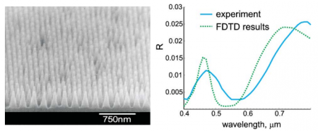
In order to model dispersive dielectric permittivity of silicon in FDTD, one can use technique described in section Fitting of dielectric function.


